

Description
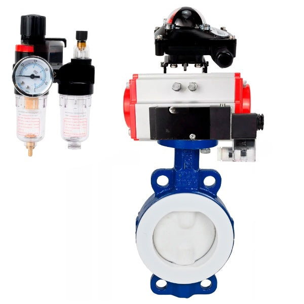
Rotary disc gate valve is designed for use as shut-off or regulating valves for flow control in heat supply systems, water supply systems, in technological processes of food, chemical, oil and gas, pulp and paper and other industries.
Operating principle: The valves are opened and closed by turning the disc by 90°. Opening is performed by turning the handle anti-clockwise, closing - clockwise. The peculiarity of the gate valves of this series is the complete covering of the flow part and disc with PTFE material, which makes it possible to exclude the contact of the working medium with the materials of the main parts.
DNOVA pneumatic double-acting rotary actuators PA-DA and pneumatic rotary actuators with return spring PA-SA are designed for automation of industrial valve control process with maximum torque up to 2128 Nm.
The pneumatic valve is used to change the direction, start, stop the compressed air flow in the pneumatic system depending on the external control action.
A distinctive feature of this series of valves is that the flow path and disc are completely coated with PTFE, which prevents the working medium from coming into contact with the materials of the main components.
Technical characteristics of butterfly valves DNOVA WBV3434Pf-2W-Fb-H, body material - Carbon steel, disk material - Carbon steel, seal - PTFE
| Characteristic | Value |
|---|---|
| Type of valve | Rotary disc |
| Diameter | 50-300 mm |
| Nominal pressure | 16 bar |
| Operating temperature | -10 to +150°C |
| Application | water supply, heat supply, chemical industry, oil and gas industry, food industry, pulp and paper industry |
| Connection type | Wafer |
| Control type | Pneumatic actuator |
| Leakage class | A |
| Country of origin | China |
| Service life | 10 years |
| Warranty | 12 months |
Dimensions and dimensions of butterfly valves DNOVA WBV3434Pf-2W-Fb-H, body material - Carbon steel, disk material - Carbon steel, seal - PTFE
| DN | L, mm | D1, mm | D2, mm | Z-Ød, mm | H1, mm |
| DN50 | 43 | 125 | 100 | 2-Ø18 | 80 |
| DN65 | 46 | 145 | 120 | 2-Ø18 | 90 |
| DN80 | 46 | 160 | 135 | 4-Ø18 | 100 |
| DN100 | 52 | 180 | 155 | 4-Ø18 | 110 |
| DN125 | 56 | 210 | 185 | 4-Ø18 | 120 |
| DN150 | 56 | 240 | 210 | 4-Ø18 | 150 |
| DN200 | 60 | 295 | 265 | 4-Ø18 | 170 |
| DN250 | 68 | 355 | 320 | 4-Ø18 | 190 |
| DN300 | 78 | 410 | 375 | 4-Ø18 | 230 |
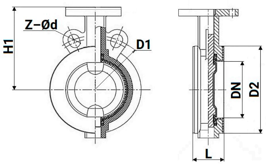
Table of parts and materials for butterfly valves DNOVA WBV3434Pf-2W-Fb-H, body material - Carbon steel, disk material - Carbon steel, seal - PTFE
| № | Part Name | Material |
|---|---|---|
| 1 | Body |
DN50÷200 – Carbon steel WCB, lined with PTFE; |
| 2 | Disc | DN50÷200 – Carbon steel WCB, lined with PTFE; DN150÷200 – Carbon steel WCB, lined with PTFE; DN250÷300 – Carbon steel WCB, lined with PFA (enhanced PTFE) |
| 3 | Shaft | DN50÷200 – Stainless steel 2Cr13; DN150÷250 – Stainless steel 2Cr13; DN300 – Steel 45 |
| 4 | Seat seal | PTFE |
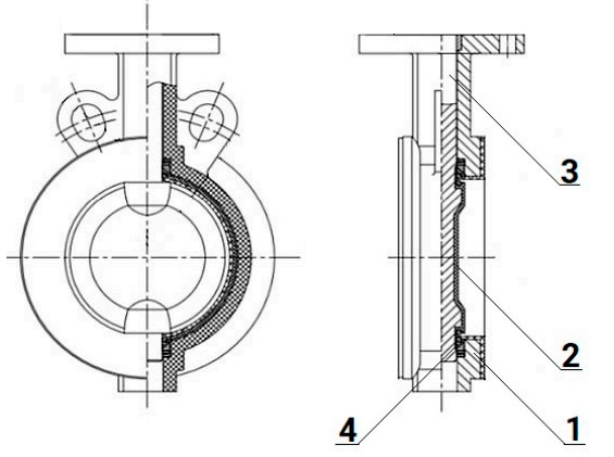
Parts and materials sketch for butterfly valves DNOVA WBV3434Pf-2W-Fb-H, body material - Carbon steel, disk material - Carbon steel, seal - PTFE
Technical data of SA pneumatic actuators with return springs:
| Type of pneumatic actuator | SA - with return springs |
| Nominal pressure PN, bar | 12 |
| Working pressure, bar | 2...8 |
| Working medium | filtered compressed air |
| Maximum particle diameter of the working medium, µm2 | ≤30 |
| Ambient temperature, ⁰C | -20 to +80 |
| Swivel angle, ° | 0 - 90 |
| Swivel angle adjustment, % | ±5 |
| Position indicator | open/closed |
| Top connection standard | NAMUR |
| Air connection standard | NAMUR |
| Average life, cycles closed/open | 70 000 (for non-aggressive media and medium pressure and temperature values) |

SA pneumatic actuators rotary with return springs
Dimensions and mounting dimensions of SA pneumatic actuators with return springs:
| Model | A, mm | B, mm | C, mm | D, mm | E, mm | F, mm | G, mm | H, mm |
| PA-x-052 | 30 | 41,5 | 65,5 | 72 | 92 | 65 | 30 | 80 |
| PA-x-065 | 36 | 47 | 81 | 88 | 108 | 72 | 30 | 80 |
| PA-x-083 | 46 | 57 | 98,5 | 108,7 | 128,7 | 92 | 30 | 80 |
| PA-x-105 | 57,5 | 64 | 122,5 | 133 | 153 | 109,5 | 30 | 80 |
| PA-x-130 | 67,5 | 74,5 | 145,5 | 155 | 185 | 127,5 | 30 | 130 |
| PA-x-140 | 75 | 77 | 161 | 172 | 202 | 137,5 | 30 | 130 |
| PA-x-160 | 87 | 87 | 184 | 197 | 227 | 159 | 30 | 130 |
| PA-x 210 | 113 | 113 | 235,5 | 255 | 285 | 210 | 30 | 130 |
| PA-x-270 | 147 | 147 | 299 | 326 | 356 | 273 | 30 | 130 |
| PA-x-300 | 162 | 174 | 330 | 350 | 380 | 312 | 30 | 130 |
| PA-x-350 | 190 | 195 | 483 | 410 | 440 | 365 | 30 | 130 |
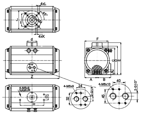
Sketch of dimensions of SA pneumatic actuators with return springs
Materials of parts of SA pneumatic actuators with return springs:
| № | Part name | Material |
| 1 | Indicator screw | ABS plastic |
| 2 | Position indicator | ABS plastic |
| 3 | Spring clip | stainless steel 304 |
| 4 | Metal washer | stainless steel 304 |
| 5 | Pressure washer | engineering plastic |
| 6 | Housing | hard anodized extruded aluminum alloy |
| 7 | Pressure washer | engineering plastic |
| 8 | Limiter | alloy steel |
| 9 | Shaft sealing ring upper | NBR |
| 10 | Upper shaft sliding ring | engineering plastic |
| 11 | Shaft | nickel plated alloy steel |
| 12 | Shaft sliding ring lower | engineering plastic |
| 13 | Shaft O-ring lower | NBR |
| 14 | Plug | NBR |
| 15 | Seal ring of adjusting screws | NBR |
| 16 | Washer of adjusting screw | stainless steel 304 |
| 17 | Lock nut of adjusting screw | stainless steel 304 |
| 18 | Adjusting screw | stainless steel 304 |
| 19 | Piston | die-cast aluminum alloy |
| 20 | Piston guide plate | engineering plastic |
| 21 | Piston sliding ring | engineering plastic |
| 22 | Piston O-ring | NBR |
| 23 | Spring set | spring steel |
| 24 | Cover O-ring | NBR |
| 25 | End cap | cast aluminum with polyester coating |
| 26 | Cover screw | stainless steel 304 |
| 27 | Stop screw | stainless steel 304 |
| 28 | Adapter | carbon steel |
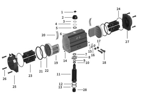
Material sketch of SA pneumatic actuators with return springs
Technical characteristics of the pneumatic distributor 4M310-08 NAMUR
| Design | Spool-type |
| Test pressure (body strength test. Not for operation!), bar | 10 |
| Working pressure (recommended range for normal operation), bar | 1.5 ÷ 8 |
| Valve type | 5/2 five-port, two-position |
| Working medium | purified air (40 µm filter fineness) |
| Operating temperature, °C | 0 to +60 |
| Actuation frequency | 5 cycles per second |
| Manual override | yes |
| Protection rating/insulation class | IP65/F |
| Connection to pneumatic actuator | NAMUR-compliant mounting surface (VDI/VDE3845) |
| Body material | anodized aluminum |
| Effective cross-sectional area, mm2 | 25 (Cv = 1.4) |
| Exhaust port dimensions (vent to atmosphere) | 2 - PT1/4” |
| Air inlet port size (to pneumatic valve) | G1/4” |
| Air outlet port size (to pneumatic actuator) | 2 x Ø19.2 mm |
| Response time, sec | 0.05 |
| Supply voltage, V | 220AC/24DC |
| Coil power | 220VAC – 5.5 VA/24VDC – 4.8 W |
| Weight, kg | 0.35 |
| Average service life, cycles | 10,000,000 |
Overall and installation dimensions of the pneumatic distributor 4M310-08 NAMUR
| A | C | D | E | F | G | H | I | K | L | J | N | M |
| mm | ||||||||||||
| 40 | 24 | 28 | 32 | 40 | 21,5 | 69 | 45 | 17,5 | 135 | 29,3 | 40 | 27 |

Sketch of the dimensions of the pneumatic distributor 4M310-08 NAMUR
Basic materials and parts of the pneumatic distributor 4M310-08 NAMUR
| № | Part Name | Material |
| 1 | Connector | Engineering plastic |
| 2 | Nut | POM + carbon steel |
| 3 | Coil | Copper |
| 4 | Control Elements | — |
| 5 | Plate | Carbon steel |
| 6 | Piston | POM |
| 7 | Control Valve Seat | Engineering plastic |
| 8 | Valve Body | Aluminum alloy |
| 9 | Spool | Aluminum alloy |
| 10 | O-Ring Seal | HNBR |
| 11 | Rear Cover | Engineering plastic |
| 12 | Filter | Synthetic material |
| 13 | Piston | POM |
| 14 | Spring | Stainless steel |
| 15 | Manual Override | Engineering plastic |
| 16 | Rear Seat | Aluminum alloy |
| 17 | Spring Seat | Aluminum alloy |
| 18 | Type C Towing Shackle | 65Mn |

Sketch of the dimensions of the pneumatic distributor 4M310-08 NAMUR
Technical parameters of limit switch unit DNOVA APL-210N EX
| Specification | Value |
|---|---|
| Limit Switch Box Model | APL-210N |
| Protection | All-weather IP65 |
| Ambient Temperature | from -40°C to +80°C |
| Cable Entry Thread | 2 x NPT1/2” |
| Terminal Block | 8 slots 0.08-2.6mm² |
| Voltage | 12V, 24V, 38V, 48V, 110V, 220V, 250V |
| Sensor | 2 SPDT electromechanical microswitches OMRON V151-1C25 |
| External Coating | Polyester coating (black) |
| Shaft | Standard (17 mm) |
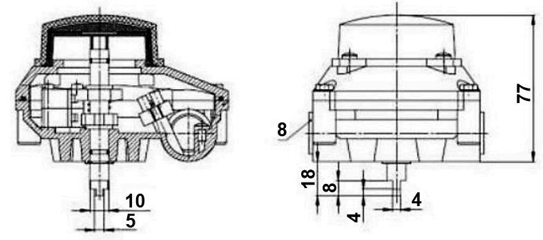
Dimensions and dimensions of limit switch unit DNOVA APL-210N EX
| Dimension | Value (mm) |
|---|---|
| Depth | 112 |
| Height | 77 |
| Width | 88 |
Technical parameters of DNOVA AFC2000 air treatment unit
| Characteristic | Value |
|---|---|
| Operating Pressure | 8 bar |
| Maximum Pressure | 10 bar |
| Adjustable Pressure Range | 0.5...9 bar |
| Burst Pressure | 15 bar |
| Operating Temperature | -5°C to +60°C |
| Air Connection | 1/4" |
| Filtered Particle Size | 40 µm |
| Oil Viscosity | ISO VG 32 |
Dimensions and dimensions of DNOVA AFC2000 air treatment unit
| Model | AFC2000 |
| A, mm | 162 |
| B, mm | 88 |
| C, mm | 139 |
| D, mm | 31 |
| E, mm | 53.5 |
| F, mm | 12 |
| G, mm | 8 |
| H, mm | 7 |
| I, mm | 13.3 |
| J, mm | 39 |
| K, mm | 5 |
| L, mm | 40 |
| M, mm | 32 |
| N, mm | 53 |
| O, mm | 29 |
| P, mm | 6 |
| R, mm | 41.5 |

Specifications
Delivery
The cost and delivery time for your order depend on several factors, including the specific product you are ordering, the quantity, and the country of destination. Each product may have different manufacturing lead times and shipping requirements, which can affect the overall delivery schedule.
To get the most accurate and up-to-date information on delivery costs and timelines, we recommend contacting our sales managers. They will be happy to provide you with a detailed quote and estimated delivery time based on your specific requirements.
Please feel free to reach out to us for any questions or further assistance regarding your order.