
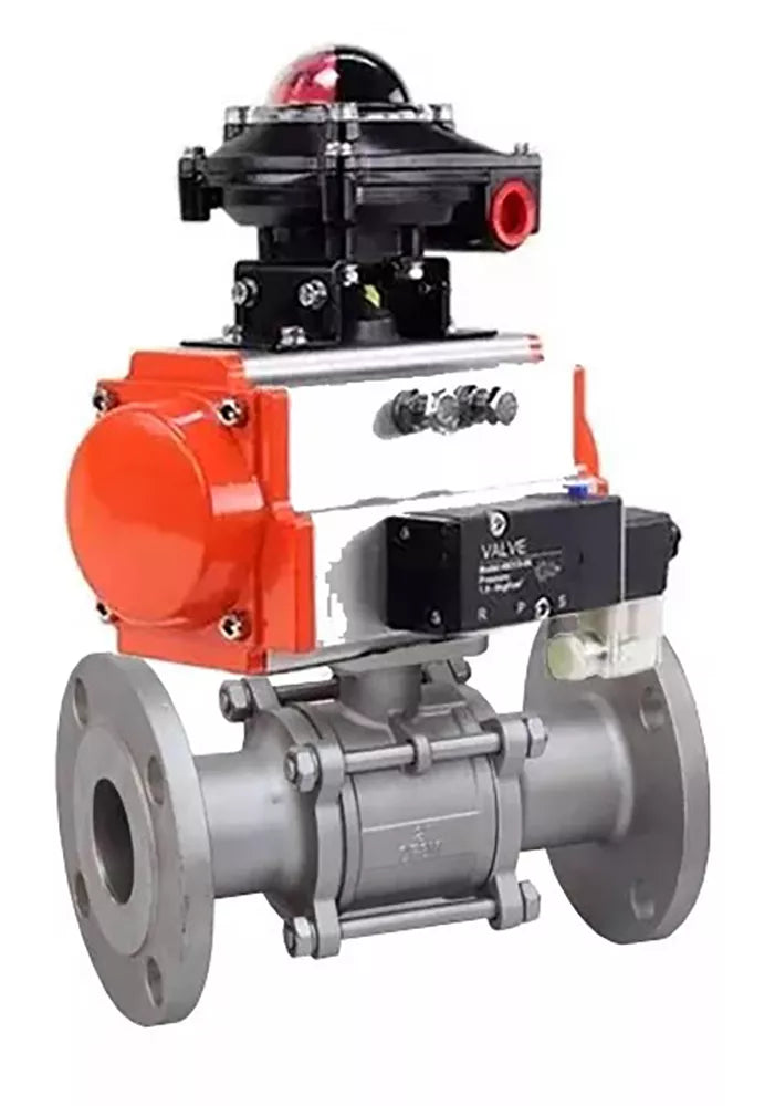
How it works
Double-acting rotary actuator


Two-way ball valve


5/2 single-solenoid pilot


Limit-switch box


The number that matters
Max. medium temperature
200°C
The highest medium temperature this valve is rated for.
Construction
Parts and materials
Applications
Media and industries
- Water
- Steam
- Oil Products
- Liquid Media
- Neutral Media
- Gaseous Media
The ball valve is used as a shut-off valve in heat supply systems, water supply systems, in steam, fuel and pneumatic systems with compressed air and neutral gases. Installation of valves of this series is possible in systems transporting liquid and gaseous media (water, oil, oils, steam, air, alcohols, glycol, etc.), non-aggressive to the materials of the valve.
Pneumatic actuators PA-DA are designed to automate the process of controlling industrial shut-off valves - valves, ball valves. Pneumatic actuators DNOVA are designed for use both indoors and outdoors. All internal and external parts have an anti-corrosion coating.
The DNOVA APL-510N-EX limit switch unit is an electrical device designed to open and close the working circuit and to visualize the positions of the shut-off element of pipeline valves. As a rule, a sealed box contains two mechanical switches rated for up to 250 V, which monitor the position of the actuator rod and signal in extreme positions. They are mounted on top of the actuator surface. In the upper part of the limit switch unit there is a two-color hemisphere of the visual indicator. If the connected pipeline valve is closed, then only the red part of the hemisphere with the inscription CLOSED is visible; if open, only the yellow part with the inscription OPEN. This visual indicator is clearly visible from afar, which simplifies the inspection of the equipment, and the color difference between the open and closed positions reduces the likelihood of erroneous perception of information. Thanks to the use of the LSU, it becomes possible to transmit information about the position of pipeline valves (open/closed) to automated control systems, which increases the reliability of the system as a whole and simplifies diagnostics when faults are detected.
Technical data of ball valves DNOVA BV3232P(2pc)-FP-F-ISO-H PA-DA 4M310-08 24V APL-510N Ex
| Nominal diameter DN, mm | 40 – 300 |
| Nominal pressure PN, MPa (kg/cm2) | 1.6 (16) |
| Direction of flow | bilateral |
| Temperature of working environment t, °C |
-20 to +85 for NBR -20 to +120 for EPDM -10 to +180 for PTFE |
| Working environment |
EPDM: cold and hot water, air without impurities of oil and fat, other environments neutral to the material PTFE: water, alkalis, acids, solvents and oxidizers NBR: water, mineral oils, hydrocarbons, oils, fats |
| Connection to the pipeline | interflange |
Sketch of detailing of ball valves DNOVA BV3232P(2pc)-FP-F-ISO-H PA-DA 4M310-08 24V APL-510N Ex

Materials of parts of ball valves DNOVA BV3232P(2pc)-FP-F-ISO-H PA-DA 4M310-08 24V APL-510N Ex
| No. | Detail | Material |
|---|---|---|
| 1 | Frame | stainless steel SS316 |
| 2 | Ball seal | RPTFE |
| 3 | Ball | stainless steel SS316 |
| 4 | Bolt | stainless steel SS304 |
| 5 | Sealing | PTFE |
| 6 | screw | stainless steel SS304 |
| 7 | Pipe branch | stainless steel SS316 |
| 8 | Stock | stainless steel SS316 |
| 9 | Seal | PTFE |
| 10 | Rod seal | PTFE |
| 11 | Seal | stainless steel SS304 |
| 12 | screw | stainless steel SS304 |
| 13 | Lever | stainless steel SS316, PVC |
Sketch of ball valves DNOVA BV3232P(2pc)-FP-F-ISO-H PA-DA 4M310-08 24V APL-510N Ex

Overall and installation dimensions of ball valves DNOVA BV3232P(2pc)-FP-F-ISO-H PA-DA 4M310-08 24V APL-510N Ex
| DN | d, mm | D, mm | D1, mm | D2, mm | C, mm | t, mm | L, mm | W, mm | H, mm | H1, mm | A, mm | B, mm | KxK (rod) | N-∅Z, pcs-mm |
| 15 | 15 | 95 | 65 | 45 | 16 | 2 | 115 | 127 | 79 | 8 | 36 | 42 | 9x9 | 4-∅14 |
| 20 | 20 | 105 | 75 | 58 | 18 | 2 | 120 | 127 | 83 | 9 | 36 | 42 | 9x9 | 4-∅14 |
| 25 | 25 | 115 | 85 | 68 | 18 | 2 | 125 | 165 | 94 | 14 | 42 | 50 | 11x11 | 4-∅14 |
| 32 | 32 | 140 | 100 | 78 | 18 | 2 | 130 | 165 | 115 | 15 | 42 | 50 | 11x11 | 4-∅18 |
| 40 | 38 | 150 | 110 | 88 | 18 | 3 | 140 | 186 | 115 | 17 | 50 | 70 | 14x14 | 4-∅18 |
| 50 | 50 | 165 | 125 | 102 | 20 | 3 | 150 | 186 | 120 | 20 | 50 | 70 | 14x14 | 4-∅18 |
| 65 | 65 | 185 | 145 | 122 | 19 | 3 | 170 | 260 | 151 | 22 | 70 | 102 | 17x17 | 4-∅18 |
| 80 | 76 | 200 | 160 | 138 | 21 | 3 | 180 | 321 | 158 | 21 | 70 | 102 | 17x17 | 8-∅18 |
| 100 | 99 | 220 | 180 | 158 | 21 | 3 | 190 | 321 | 188 | 20 | 70 | 102 | 17x17 | 8-∅18 |
Technical data of DA double-acting pneumatic actuators:
| Type of pneumatic actuator | DA - double-acting |
| Nominal pressure PN, bar | 12 |
| Working pressure, bar | 2...8 |
| Working medium | filtered compressed air |
| Maximum particle diameter of the working medium, µm2 | ≤30 |
| Ambient temperature, °C | -20 to +80 |
| Swivel angle, ° | 0 - 90 |
| Swivel angle adjustment, % | ±5 |
| Position indicator | open/closed |
| Top connection standard | NAMUR |
| Air connection standard | NAMUR |
| Average life, cycles closed/open | 70 000 (for non-aggressive media and medium pressure and temperature values) |
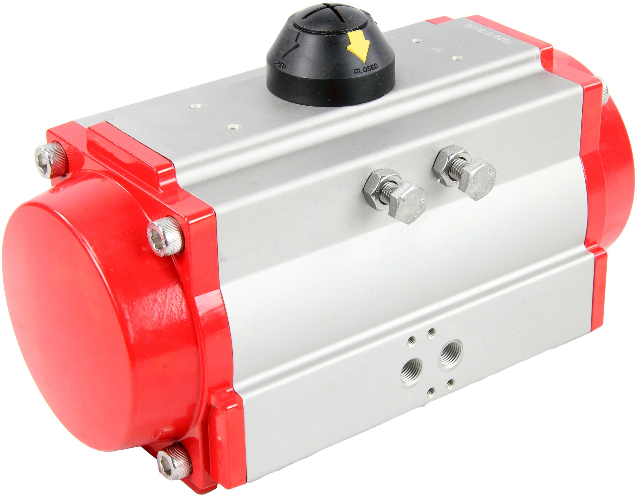
DA pneumatic actuators double-acting rotary actuators
Dimensions and mounting dimensions of DA double-acting pneumatic actuators:
| Model | A, mm | B, mm | C, mm | D, mm | E, mm | F, mm | G, mm | H, mm |
| DA-052 | 30 | 41,5 | 65,5 | 72 | 92 | 65 | 30 | 80 |
| DA-065 | 36 | 47 | 81 | 88 | 108 | 72 | 30 | 80 |
| DA-083 | 46 | 57 | 98,5 | 108,7 | 128,7 | 92 | 30 | 80 |
| DA-105 | 57,5 | 64 | 122,5 | 133 | 153 | 109,5 | 30 | 80 |
| DA-130 | 67,5 | 74,5 | 145,5 | 155 | 185 | 127,5 | 30 | 130 |
| DA-140 | 75 | 77 | 161 | 172 | 202 | 137,5 | 30 | 130 |
| DA-160 | 87 | 87 | 184 | 197 | 227 | 159 | 30 | 130 |
| DA-210 | 113 | 113 | 235,5 | 255 | 285 | 210 | 30 | 130 |
| DA-270 | 147 | 147 | 299 | 326 | 356 | 273 | 30 | 130 |
| DA-300 | 162 | 174 | 330 | 350 | 380 | 312 | 30 | 130 |
| DA-350 | 190 | 195 | 483 | 410 | 440 | 365 | 30 | 130 |
| Model | I, mm | J, mm | M, mm | N, mm | Z, mm | d, mm | K | L |
| DA-052 | 36 | 50 | 11x11 | 14 | 147 | 40 | M5x8 | M6x10 |
| DA-065 | 50 | 70 | 14x14 | 18 | 168 | 40 | M6x10 | M8x13 |
| DA-083 | 50 | 70 | 17x17 | 21 | 204 | 40 | M6x10 | M8x13 |
| DA-105 | 70 | 102 | 22x22 | 26 | 268 | 40 | M8x13 | M10x16 |
| DA-130 | 70 | 102 | 22x22 | 26 | 301 | 55 | M8x13 | M10x16 |
| DA-140 | 102 | 125 | 27x27 | 31 | 390 | 55 | M10x16 | M12x20 |
| DA-160 | 102 | 125 | 27x27 | 31 | 458 | 55 | M10x16 | M12x20 |
| DA-210 | - | 140 | 36x36 | 40 | 532 | 80 | - | M16x25 |
| DA-270 | - | 165 | 46x46 | 50 | 718 | 80 | - | M20x25 |
| DA-300 | - | 165 | 46x46 | 50 | 760 | 80 | - | M20x25 |
| DA-350 | 165 | 254 | 46x46 | 50 | 920 | 80 | M20x25 | 8xM16x25 |
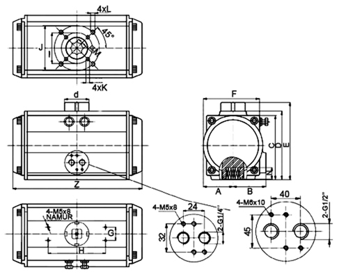
Sketch of dimensions of DA double-acting pneumatic actuators
Materials of parts for DA double-acting pneumatic actuators:
| № | Part name | Material |
| 1 | Indicator screw | ABS plastic |
| 2 | Position indicator | ABS plastic |
| 3 | Spring clip | stainless steel 304 |
| 4 | Metal washer | stainless steel 304 |
| 5 | Pressure washer | engineering plastic |
| 6 | Housing | hard anodized extruded aluminum alloy |
| 7 | Pressure washer | engineering plastic |
| 8 | Limiter | alloy steel |
| 9 | Shaft sealing ring upper | NBR |
| 10 | Upper shaft sliding ring | engineering plastic |
| 11 | Shaft | nickel plated alloy steel |
| 12 | Shaft sliding ring lower | engineering plastic |
| 13 | Shaft O-ring lower | NBR |
| 14 | Plug | NBR |
| 15 | Seal ring of adjusting screws | NBR |
| 16 | Washer of adjusting screw | stainless steel 304 |
| 17 | Lock nut of adjusting screw | stainless steel 304 |
| 18 | Adjusting screw | stainless steel 304 |
| 19 | Piston | die-cast aluminum alloy |
| 20 | Piston guide plate | engineering plastic |
| 21 | Piston sliding ring | engineering plastic |
| 22 | Piston O-ring | NBR |
| 23 | Spring set | spring steel |
| 24 | Cover O-ring | NBR |
| 25 | End cap | cast aluminum with polyester coating |
| 26 | Cover screw | stainless steel 304 |
| 27 | Stop screw | stainless steel 304 |
| 28 | Adapter | carbon steel |
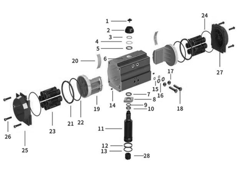
Material sketch of DA double-acting pneumatic actuators
Technical characteristics of the pneumatic distributor 4M310-08 NAMUR
| Design | Spool-type |
| Test pressure (body strength test. Not for operation!), bar | 10 |
| Working pressure (recommended range for normal operation), bar | 1.5 ÷ 8 |
| Valve type | 5/2 five-port, two-position |
| Working medium | purified air (40 µm filter fineness) |
| Operating temperature, °C | 0 to +60 |
| Actuation frequency | 5 cycles per second |
| Manual override | yes |
| Protection rating/insulation class | IP65/F |
| Connection to pneumatic actuator | NAMUR-compliant mounting surface (VDI/VDE3845) |
| Body material | anodized aluminum |
| Effective cross-sectional area, mm2 | 25 (Cv = 1.4) |
| Exhaust port dimensions (vent to atmosphere) | 2 - PT1/4” |
| Air inlet port size (to pneumatic valve) | G1/4” |
| Air outlet port size (to pneumatic actuator) | 2 x Ø19.2 mm |
| Response time, sec | 0.05 |
| Supply voltage, V | 220AC/24DC |
| Coil power | 220VAC – 5.5 VA/24VDC – 4.8 W |
| Weight, kg | 0.35 |
| Average service life, cycles | 10,000,000 |
Overall and installation dimensions of the pneumatic distributor 4M310-08 NAMUR
| A | C | D | E | F | G | H | I | K | L | J | N | M |
| mm | ||||||||||||
| 40 | 24 | 28 | 32 | 40 | 21,5 | 69 | 45 | 17,5 | 135 | 29,3 | 40 | 27 |

Sketch of the dimensions of the pneumatic distributor 4M310-08 NAMUR
Basic materials and parts of the pneumatic distributor 4M310-08 NAMUR
| № | Part Name | Material |
| 1 | Connector | Engineering plastic |
| 2 | Nut | POM + carbon steel |
| 3 | Coil | Copper |
| 4 | Control Elements | — |
| 5 | Plate | Carbon steel |
| 6 | Piston | POM |
| 7 | Control Valve Seat | Engineering plastic |
| 8 | Valve Body | Aluminum alloy |
| 9 | Spool | Aluminum alloy |
| 10 | O-Ring Seal | HNBR |
| 11 | Rear Cover | Engineering plastic |
| 12 | Filter | Synthetic material |
| 13 | Piston | POM |
| 14 | Spring | Stainless steel |
| 15 | Manual Override | Engineering plastic |
| 16 | Rear Seat | Aluminum alloy |
| 17 | Spring Seat | Aluminum alloy |
| 18 | Type C Towing Shackle | 65Mn |

Sketch of the dimensions of the pneumatic distributor 4M310-08 NAMUR
Characteristics of the APL-510N-EX limit switch unit
| Parameter | Meaning |
| Frame |
All-weather IP67/ NEMA4 4X,7,9 explosion-proof E EX d IIC T6 |
| Compatible devices |
- quarter-turn pneumatic actuators; - any actuators with a shaft rotation of 90° |
| Full rotation angle | 90° |
| Cable entries | 2 x NPT 3/4” |
| Electrical connection | screw clamp terminals 8 points (0.08 – 2.5) mm2 |
| Cable entry thread | 2 x NPT 3/4” |
| Visual indicator type | two-color hemisphere: OPEN - yellow CLOSED - red |
| Switches/sensors | two mechanical switches two proximity sensors |
| Nominal voltage, V | 250 |
| Rated current, A | 16 |
| Permissible ambient temperature, °C | from -20 to +66 |
| Average resource, cycles | 10,000,000 |
| Weight, kg | 1.8 |
- Port opening
- full bore
- Body material
- Stainless steel AISI 316
- Maximum allowable temperature
- 200 °C
- Connection type
- Flanged
- Control type
- Pneumatically actuated
- Operating environment
- Water, Steam, Oil Products, Liquid Media, Neutral Media, and Gaseous Media
- Type of seal
- PTFE
- Voltage
- 24 V
- Explosion-proof
- have
- Torque
- 176 Nm
- Limit switches
- have
- Type of pneumatic actuator
- double action
- Country of origin
- China
Production. Usually 7–14 business days after you approve the quotation and pay. Made-to-specification items are confirmed in the quotation.
Freight. Not charged at checkout. A manager quotes air and sea freight to your port or airport, and nothing ships until you approve the price and the freight.
To North America. From approval and payment to the destination port or airport: air 14–24 days, sea 32–60 days. Estimates, not guarantees.
Terms. EXW Ningbo or FOB Ningbo Port; CIF on request. The agreed term is written on the Proforma Invoice.
Total items
Product subtotal